In this article we will discuss the multimeter symbols on a multimeter and what there symbols mean. We will be using a very popular multimeter the fluke 177.
What is a multimeter?
A multimeter is a tool used to measure a multiple values related to electricity, hence the name multimeter. Most multimeters measure Voltage (V), Amperage (A), Resistance (Ohms), Continuity. A multimeter can have more functions but these are the most used.
We will use a multimeter with more functions when explaining there symbols. There are two types of multimeters used, a digital multimeter and analog multimeter. Digital multimeters are most commonly used today like the one in the image below.
Multimeter symbols and their meanings
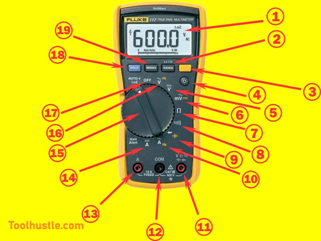
| Number | Symbol meaning | Description |
| 1 | Digital display | Displays the status of what is being metered and functions of meter. |
| 2 | Range Button | Allows you to select a range to measure a value in |
| 3 | Function Switch Button | Switches to the secondary option where applicable. Highlighted by the yellow symbol. |
| 4 | Backlight | Disables and enables the backlight feature. |
| 5 | DC Voltage | Measures DC voltage, indicated by the V with a straight and dashed line on top. |
| 6 | AC Millivolts | Measures Millivolts for AC current indicated by the mV with the ~ symbol on top. The secondary function is used to measures DC Millivolts indicated by the straight and dashed line. |
| 7 | Ohms | Measures the amount of resistance in a circuit indicated by the Ω symbol. It gives a value measured in Ohms. |
| 8 | Continuity | Used to measure continuity in a circuit, indicated by a symbol similar to WIFI. When continuity is detected an audible noise is made followed by a change in value on the display. |
| 9 | Diode tester | Tests the status of a diode, indicated by the diode symbol. The secondary function is used to measures the capacitor indicated by the capacitor symbol. |
| 10 | AC Current | Measures AC current, indicated by the A with the ~ symbol on top. The secondary function is used to measure frequency indicated by the Hz symbol. |
| 11 | Multimeter Lead Input | Terminal input for measuring continuity, capacitance, resistance, frequency, voltage, and testing diodes. |
| 12 | Common Terminal | Multimeter lead input for all measurements |
| 13 | Current Multimeter Lead Input | Terminal input for measuring AC and DC current up to 10A |
| 14 | DC Current | Measures the DC current |
| 15 | Rotary Dial | A rotary dial that switches between different functions of the multimeter |
| 16 | AC Voltage | Measures AC voltage indicated by the A and ~ symbol on top, the secondary function is used to measure frequency indicated by the Hz symbol |
| 17 | OFF position | When the rotary dial is in this position the multimeter will turn OFF. |
| 18 | HOLD Button | Pauses on the the value displayed in the digital display until HOLD function stopped. |
| 19 | MIN/MAX Button | Records the minimum and maximum values read by the multimeter. |